THE
RESONANT CONVERTERS
|
The
resonant switching topology is, to date, one of the
most
efficient solutions for designing switch mode power supplies.
|
|
"Although
in existence for many years, only recently has the LLC and
LCC resonant
converter (in particular in its half-bridge implementation)
gained in the popularity it certainly deserves. In
many applications, such as flat panel TVs, PCs and
notebooks,
LED
drivers,
where the efficiency, power density and cost requirements are getting increasingly stringent, the resonant half-bridge
with its many benefits and very few drawbacks is an excellent
solution.
Also in applications with large ouput voltage ranges, the LCC topology in particular is the most suitable."
|
|
The
introduction of new regulations, both voluntary and mandatory,
has brought about a revaluation of the LLC and LCC resonant topology.
|
In
LED lighting (to name just one of the infinite applications)
the need for more and more efficient power supply systems is
pushing power designers in this direction.
|
All
the most important manufacturers of active components
on the SMPS controller market have included efficient
chips in their product catalogues. Also some new families of
Mosfets with specific characteristics for resonant converters
have been developed.
|
With
an effectively contained degree of circuit complexity, they
allow the realization of power supplies with 93-96% efficiency
(which can be further improved using synchronous rectifiers
instead of rectification diodes) and reduce EMI/EMC issues
compared to other topologies thanks to "Zero Voltage
Switching" and to the substantially sinusoidal high
frequency currents.
|
"Generally
speaking, resonant converters are switching converters that
include a tank circuit actively participating in determining
input-to-output power flow."
|
The
operating principle is based on the characteristic gain curve
of the resonant tank", which allows to change the gain through
a moderate variation of the switching frequency, thus resulting
in an effective regulation of output voltage or current in
relation to load and input voltage changes.
|
The
resonant "tank" is a set of two inductive elements
and one capacitor (LLC) or two inductive elements and two
capacitors (LCC).
Using
a conventional transformer, the two inductive elements are
the magnetizing inductance of the transformer and a discrete
resonant inductor.
On the other hand, the “integrated transformer”
exploits part of the leakage inductance, eliminating the need
for a discrete resonant inductor.
|
The
use of an integrated transformer is therefore much more convenient in terms of cost, size and energy efficiency.The
specific features of the integrated transformer are described below.
|
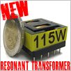
To
give an idea of the advantages, a well-designed 180 W
integrated transformer can measure less than 28x29x23 mm,
with costs that are obviously more competitive compared
to solutions that use a discrete inductance.
|
It
is evident that the only possible reason leading to the use of
a convetional transformer is the difficulty of designing a
coherent and optimized tank.
|
In
most electronic equipment from the largest manufacturers the
inductive components are well structured. Usually in these cases
a time-consuming optimization is performed through FEM tools.
Despite potentially having access to the same technologies, many
other manufacturers make use of very poor magnetic components.
The level of optimization is not the same because of a lack of
highly specific skills, efficient design tools or big budgets.
Sometime all of these.
|
|
BENEFITS
|
-
typical range of efficiency for the simplest circuitry 94-96%,
with possible improvements through synchronous rectification
and other small adjustments;
|
-
using correctly sized magnetic components, the design is
rapid and much simplified;
|
-
the current waveform at high frequencies is basically
sinusoidal, with significant reductions in harmonics compared
to other topologies;
|
-
MOSFET commutation ON "ZVS" (Zero Voltage Switching)
with associated elimination of commutation loss,
reduction/elimination of dissipators and reduction of stress
and EMI, which often cause the most hostile design problems;
|
-
the possibility to reduce consumption with low/zero load by
using the functions "burst mode" and "PFC
stop" implemented on many controllers;
|
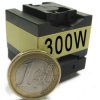
-
the possibility of optimal sizing for continuous and temporary
power, including some significant improvements on conventional
solutions (e.g. an optimised transformer with volume similar to
a classic EF25 can easily supply up to 500Wpk and more);
|
-
compared to other topologies, LLC and LCC power supplies have
smaller dimensions with a notable reduction in EMI/EMC issues;
|
-
typical cost savings on dissipators, EMC filters, smaller
transformers-PCB-enclosures.
|
|
DRAWBACKS
|
-
the cost and performance of a resonant power supply largely
depends on the the tank and the inductive components. Even a
good level of skill may not be enough for an optimal design;
|
-
the resonant controller is more costly than the flyback counterpart;
|
-
two MOSFETs (half bridge) are required, rather than the single
one required for the Flyback topology
|
(however,
even disregarding the efficiency improvement, the related cost
increase tends to cancel itself - or even turn to a saving - thanks to
the cost reduction on other components).
|
|
Lots
of documents are available to extend the topic; let's take a
look at some examples.
|
Here
are some quick design considerations from
Fairchild
Semiconductor ® and
Texas
Instruments ®.
|
Here
are some useful and more comprehensive application notes
from ST
Microelectronics ®, Fairchild
Semiconductor ® and Infineon
®.
|
|
THE
INTEGRATED TRANSFORMER
|
|
The
so-called "integrated resonant transformers", make
use of leakage inductance (which normally represents an
undesirable parasitic effect) instead of a discrete inductor,
integrating two of the three resonant tank elements in just one
inductive component.
|
In
addition to convenience in terms of cost and dimensions, it
must be highlighted that the magnetic flux of the leakage
inductance fundamentally travels through free air, thus
eliminating every problem linked to the core saturation.
For a discrete inductor it is not the case.
|
In
order to achieve good results, the design structure and details
must be skillfully managed so as to obtain the required leakage
inductance, in relation to all the other design parameters,
under conditions of minimal power loss.
|
In
many cases, empirical experience and generic methods of calculation
can lead to acceptable approximations; but not in those applications
where high efficiency is strictly required.
|
In
these cases, a few more lost Watts - or sometimes a fraction of a
Watt - can significantly affect the power supply's overall efficiency.
It can easily compromise the careful choices made during the design
of the converter.
|
Optimal
efficiency for inductive components can only be achieved by
surpassing a number of simplified design methodologies, such as
the equal division of the power loss target between the core and
the copper.
|
Literature
and experience teach us that the best efficiency point can be
identified via the "ad hoc" definition of power loss depending on
several trade-offs.
|
In
the specific case of integrated transformers, there are a
number of restrictions requiring close cooperation with
the manufacturer of inductive components.
|
The
definition of the best parameters for a resonant tank cannot be
made without considering the restrictions linked to the structural
elements of each transformer - first and foremost the curve showing
the relationship between inductance and leakage inductance.
|
Without
this dialogue, you will - at best - be forced to work with an
inappropriate inductance value, which can result in a bad design.
|
The
most critical issue in the design of integrated transformers is
the realistic calculation of winding losses, without which any
design optimization becomes unfeasible. With this calculation,
the Eddy Current loss resulting from the "proximity effect"
should be considered as well as the "skin effect".
|
|
A
lack of consideration of these issues, or a lack of know-how
in magnetic component design, often leads to designing low-efficiency
transformers (and power supplies) from an economical, energy and
dimensional standpoint, with an undesirable waste of resources.
|
|
The
following comparative test reports show how it's possible to
increase efficiency thanks to an optimized integrated transformer.
Take
a look at some interesting examples:
|
https://www.itacoilweb.com/files/Test_comparativo_DB_ST_LCC_300W_LLL09V1A.pdf
|
https://www.itacoilweb.com/files/TEA2016DB1519v2_slides.pdf
|
Other
examples here:
https://www.itacoilweb.com/portfolio/improved-demo-boards/
|
|
For
more info about the integrated resonant transformers click on
the following links:
https://www.itacoilweb.com/llc-lcc-resonant-power-supplies/
https://www.itacoilweb.com/llc-lcc-resonant-topologies/
|
|
THE
PFC INDUCTOR
|
|
The
active PFC stage on the input of a SMPS is often mandatory.
|
There
are also some critical design considerations about this
component, especially for some of the most used types.
|
The
most popular type of PFC adopted for power levels up to 200-300
W is the "Transition Mode" (also named "Critical
Mode" or "Boundary mode"), where the usual core
loss calculation methods cannot be used due to the complexity
of the current waveform.
|
In
fact, even at a constant load, the current has an almost
triangular wave shape, but with continuously variable frequency
and amplitude depending on the instantaneous input voltage value
[|sen (VinRMS)|].
On
the other hand, with “continous mode” (CCM) PFC flux
sub-loop and variable DC bias occurs, introducing other critical
aspects on the power loss calculation.
|
It
must be considered that the power loss curves published by the
manufacturers of magnetic cores refer to sinusoidal waveforms
as well as specific frequencies and temperatures and therefore
are not directly applicable. In this case advanced calculation
methods are needed.
|
Additionally,
the previously mentioned problems about the calculation of power loss in the windings
also exist for the PFC inductor.
|
At
this point it is clear that an optimal design requires the access
to specific resources and tools, often not available in electronic
design teams.
|
|
|
More
info about PFC inductors here:
https://www.itacoilweb.com/portfolio_category/active-pfc-inductors/
|
|
Everything
about PCB transformers and inductors on www.itacoilweb.com
|

|